Search This Blog

Tuesday, 5 August 2014

Wireless Lan (802.11)

Wireless Lan(802.11)

Wireless networking is a rapidly evolving technology for connecting computers.the possibilities for building wireless networks are almost endless, ranging from using infrared signals within a single building to constructing a global network from a grid of low-orbit satellites. 

802.11 supports additional features (e.g., time-bounded services, power management, and security mechanisms), but we focus our discussion on its base functionality.

Physical Properties

802.11 was designed to run over three different physical media—two based on spread spectrum radio and one based on diffused infrared.

The idea behind spread spectrum is to spread the signal over a wider frequency band than normal, so as to minimize the impact of interference from other devices. (Spread spectrum was originally designed for military use, so these “other devices” were often attempting to jam the signal.)

A first technique frequency hopping is a spread spectrum technique that involves transmitting the signal over a random sequence of frequencies; that is, first transmitting at one frequency, then a second, then a third, and so on.

A second spread spectrum technique, called direct sequence, achieves the same effect by representing each bit in the frame by multiple bits in the transmitted signal. For each bit the sender wants to transmit, it actually sends the exclusive-OR of that bit and n random bits. As with frequency hopping, the sequence of random bits is generated by a pseudorandom number generator known to both the sender and the receiver. The transmitted values, known as an n-bit chipping code.

The third physical standard for 802.11 is based on infrared signals. The transmission is diffused, meaning that the sender and receiver do not have to be aimed at each other and do not need a clear line of sight. This technology has a range of up to about 10 m and is limited to the inside of buildings only.

Collision Avoidance

The problem is more complicated in a wireless network, Collision detection is not feasible since all nodes are not within the reach of each other. 

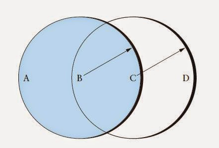
                                                          Example wireless network.


Hidden Station
  • Suppose station B is sending data to A. At the same time, station C also has data to send to station A.
  • Since B is not within the range of C, it thinks the medium is free and sends its data to A. Frames from B and C collide at A. Stations B and C are hidden from each other.
Exposed Station
  • Suppose station A is transmitting to station B and station C has some data to send to station D, which can be sent without interfering the transmission from A to B.
  • Station C is exposed to transmission from A and it hears what A is sending and thus refrains from sending, even if the channel is available
Multiple Access with Collision Avoidance (MACA)
  • The idea is for the sender and receiver to exchange short control frames with each other, so that stations nearby can avoid transmitting for the duration of the data frame.
  • The control frames used for collision avoidance is Request to Send (RTS) and Clear to Send (CTS).
  • Any station hearing RTS is close to sender and remains silent long enough for CTS to be transmitted back.
  • Any station hearing CTS remains silent during the upcoming data transmission.
  • The receiver sends an ACK frame to the sender after successfully receiving a frame.
  • If RTS frames from two or more stations collide, then they do not receive CTS. Each node waits for a random amount of time and then tries to send RTS again
Handshake for hidden & exposed station
  • B sends an RTS containing name of sender, receiver & duration of transmission.
  • It reaches A, but not C.
  • The receiver A acknowledges with a CTS message back to the sender B echoing the duration of transmission and other information.
  • The CTS from A is received by both B and C. B starts to transmit data to A.
  • C knows that some hidden station is using the channel and refrains from transmitting.
  • The handshaking messages RTS and CTS does not help in exposed stations because C does not receive CTS from D as it collides with data sent by A.


Distribution System 

  • In wireless network, nodes are mobile and the set of reachable nodes change with time.
  • Mobile nodes are allowed to connect with a wired network infrastructure called access points (AP).
  • Access points are connected to each other by a distribution system (DS) such as ethernet, token ring, etc.
  • Two nodes communicate directly with each other if they are reachable (eg, A and C)
  • Communication between two stations in different APs occurs via two APs (eg, A and E)
                                            Access points connected to a distribution network.

The technique for selecting an AP is called scanning and involves the following four steps:

  1. The node sends a Probe frame.
  2. All APs within reach reply with a Probe Response frame.
  3. The node selects one of the access points and sends that AP an Association Request frame.
  4. The AP replies with an Association Response frame.
The mechanism just described is called active scanning since the node is actively searching for an access point.APs also periodically send a Beacon frame that advertises the capabilities of the access point; these include the transmission rates supported by the AP. This is called passive scanning, and a node can change to this AP based on the Beacon frame simply by sending it an Association Request frame back to the access
point.

Frame Format

802.11 frame format.

  • Control--contains subfields that includes type (management, control or data), subtype (RTS, CTS or ACK) and pair of 1-bit fields ToDS and FromDS.
  • Duration--specifies duration of frame transmission.
  • Addresses--The four address fields depend on value of ToDS and FromDS subfields.
    • When one node is sending directly to another, both DS bits are 0, Addr1 identifies the target node, and Addr2 identifies the source node
    • When both DS bits are set to 1, the message went from a node onto the distribution system, and then from the distribution system to another node. Addr1 contains ultimate destination, Addr2 contains immediate sender, Addr3 contains intermediate destination and Addr4 contains original source.
  • Sequence Control--defines sequence number of the frame to be used in flow control.
  • Payload--can contain a maximum of 2312 bytes and is based on the type and the subtype defined in the Control field
  • CRC--contains CRC-32 error detection sequence.
Fiber Distributed Data Interface (FDDI)

Fiber Distributed Data Interface (FDDI)

The Fiber Distributed Data Interface (FDDI) specifies a 100-Mbps token-passing, dual-ring LAN using fiber-optic cable. FDDI is frequently used as high-speed backbone technology because of its support for high bandwidth and greater distances than copper.

FDDI uses dual-ring architecture with traffic on each ring flowing in opposite directions (called counter-rotating). The dual rings consist of a primary and a secondary ring. During normal operation, the primary ring is used for data transmission, and the secondary ring remains idle. the primary purpose of the dual rings is to provide superior reliability and robustness. 


FDDI Transmission Media 

FDDI uses optical fiber as the primary transmission medium, but it also can run over copper cabling. FDDI over copper is referred to as Copper-Distributed Data Interface (CDDI). Optical fiber has several advantages over copper media. In particular, security, reliability, and performance all are enhanced with optical fiber media because fiber does not emit electrical signals. A physical medium that does emit electrical signals (copper) can be tapped and therefore would permit unauthorized access to the data that is transiting the medium. In addition, fiber is immune to electrical interference from radio frequency interference (RFI) and electromagnetic interference (EMI). Fiber historically has supported much higher bandwidth (throughput potential) than copper, although recent technological advances have made copper capable of transmitting at 100 Mbps. Finally, FDDI allows 2 km between stations using multimode fiber, and even longer distances using a single mode. 

FDDI defines two types of optical fiber: single-mode and multimode. A mode is a ray of light that enters the fiber at a particular angle. Multimode fiber uses LED as the light-generating device, while single-mode fiber generally uses lasers. 

Multimode fiber allows multiple modes of light to propagate through the fiber. Because these modes of light enter the fiber at different angles, they will arrive at the end of the fiber at different times. This characteristic is known as modal dispersion. Modal dispersion limits the bandwidth and distances that can be accomplished using multimode fibers. For this reason, multimode fiber is generally used for connectivity within a building or a relatively geographically contained environment. 

Single-mode fiber allows only one mode of light to propagate through the fiber. Because only a single mode of light is used, modal dispersion is not present with single-mode fiber. Therefore, single-mode fiber is capable of delivering considerably higher performance connectivity over much larger distances, which is why it generally is used for connectivity between buildings and within environments that are more geographically dispersed.


FDDI Specifications 

FDDI specifies the physical and media-access portions of the OSI reference model. FDDI is not actually a single specification, but it is a collection of four separate specifications, each with a specific function. Combined, these specifications have the capability to provide high-speed connectivity between upper-layer protocols such as TCP/IP and IPX, and media such as fiber-optic cabling. 

FDDI's four specifications are the Media Access Control (MAC), Physical Layer Protocol (PHY), Physical-Medium Dependent (PMD), and Station Management (SMT) specifications. The MAC specification defines how the medium is accessed, including frame format, token handling, addressing, algorithms for calculating cyclic redundancy check (CRC) value, and error-recovery mechanisms. The PHY specification defines data encoding/decoding procedures, clocking requirements, and framing, among other functions. The PMD specification defines the characteristics of the transmission medium, including fiber-optic links, power levels, bit-error rates, optical components, and connectors. The SMT specification defines FDDI station configuration, ring configuration, and ring control features, including station insertion and removal, initialization, fault isolation and recovery, scheduling, and statistics collection. 


FDDI Station-Attachment Types

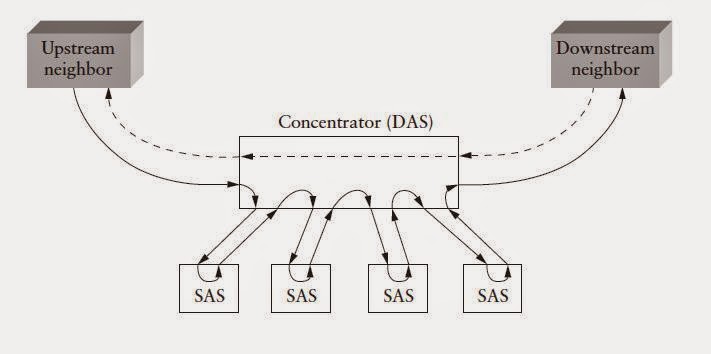
One of the unique characteristics of FDDI is that multiple ways actually exist by which to connect FDDI devices. FDDI defines four types of devices: single-attachment station (SAS), dual-attachment station (DAS), single-attached concentrator (SAC), and dual-attached concentrator (DAC). 

An SAS attaches to only one ring (the primary) through a concentrator. One of the primary advantages of connecting devices with SAS attachments is that the devices will not have any effect on the FDDI ring if they are disconnected or powered off.. 

Each FDDI DAS has two ports, designated A and B. These ports connect the DAS to the dual FDDI ring. Therefore, each port provides a connection for both the primary and the secondary rings. As you will see in the next section, devices using DAS connections will affect the rings if they are disconnected or powered off. 

An FDDI concentrator (also called a dual-attachment concentrator [DAC]) is the building block of an FDDI network. It attaches directly to both the primary and secondary rings and ensures that the failure or power-down of any SAS does not bring down the ring. This is particularly useful when PCs, or similar devices that are frequently powered on and off, connect to the ring. 


                                                      SASs connected to a concentrator.

FDDI Fault Tolerance

FDDI provides a number of fault-tolerant features. In particular, FDDI's dual-ring environment, the implementation of the optical bypass switch, and dual-homing support make FDDI a resilient media technology.


Dual Ring

FDDI's primary fault-tolerant feature is the dual ring. If a station on the dual ring fails or is powered down, or if the cable is damaged, the dual ring is automatically wrapped (doubled back onto itself) into a single ring. When the ring is wrapped, the dual-ring topology becomes a single-ring topology. Data continues to be transmitted on the FDDI ring without performance impact during the wrap condition. 

When a single station fails, as shown in Figure 8-6, devices on either side of the failed (or powered-down) station wrap, forming a single ring. Network operation continues for the remaining stations on the ring. When a cable failure occurs, as shown in the above figure, devices on either side of the cable fault wrap. Network operation continues for all stations. 

It should be noted that FDDI truly provides fault tolerance against a single failure only. When two or more failures occur, the FDDI ring segments into two or more independent rings that are incapable of communicating with each other.
                                  Dual-fiber ring: (a) normal operation; (b) failure of the primary ring.

Dual Homing

Critical devices, such as routers or mainframe hosts, can use a fault-tolerant technique called dual homing to provide additional redundancy and to help guarantee operation. In dual-homing situations, the critical device is attached to two concentrators. 

One pair of concentrator links is declared the active link; the other pair is declared passive. The passive link stays in backup mode until the primary link (or the concentrator to which it is attached) is determined to have failed. When this occurs, the passive link automatically activates. 


FDDI Frame Fields

The following descriptions summarize the FDDI data frame and token fields illustrated in the above figure.
  • Preamble - Gives a unique sequence that prepares each station for an upcoming frame.
  • Start delimiter - Indicates the beginning of a frame by employing a signaling pattern that differentiates it from the rest of the frame.
  • Frame control - Indicates the size of the address fields and whether the frame contains asynchronous or synchronous data, among other control information.
  • Destination address - Contains a unicast (singular), multicast (group), or broadcast (every station) address. As with Ethernet and Token Ring addresses, FDDI destination addresses are 6 bytes long.
  • Source address - Identifies the single station that sent the frame. As with Ethernet and Token Ring addresses, FDDI source addresses are 6 bytes long.
  • Data - Contains either information destined for an upper-layer protocol or control information.
  • Frame check sequence (FCS) - Is filed by the source station with a calculated cyclic redundancy check value dependent on frame contents (as with Token Ring and Ethernet). The destination address recalculates the value to determine whether the frame was damaged in transit. If so, the frame is discarded.
  • End delimiter - Contains unique symbols; cannot be data symbols that indicate the end of the frame.
  • Frame status - Allows the source station to determine whether an error occurred; identifies whether the frame was recognized and copied by a receiving station.